Ti xWR1642 Traffic Monitoring
Feature Frozen Lab
This lab has been feature frozen – no new updates will occur for this lab. The lab will be removed from the toolbox in December 2019. New features and updates for Traffic Monitoring will continue to be implemented within the 18xx and 68xx Traffic Monitoring lab.
Traffic Monitoring Overview
This lab demonstrates how TI single-chip millimeter-wave (mmWave) technology can be used for robust, long-range sensing in traffic monitoring and other applications. The advanced tracking feature in the lab enables multivehicle tracking across multiple lanes. The reference design uses the IWR1642BOOST evaluation module (EVM) and integrates a complete radar processing chain onto the IWR1642 device. The processing chain includes the analog radar configuration, analog-to-digital converter (ADC) capture, low-level FFT processing, and high-level clustering and tracking algorithms.

ES2.0 devices only
This lab will only work if the IWR1642BOOST EVM has a ES2.0 device. ES2.0 devices will only work with software based on mmWave SDK version 2.0 or above. If the device is ES1.0, please download and use Industrial Toolbox Version 2.3.0.
How to determine ES Version
How to access previous versions of the Industrial Toolbox
Quickstart
The quickstart uses:
- Precompiled binaries for flashing the device using Uniflash
- Visualizer as .exe
1. Hardware and Software Requirements
Hardware
| Item | Details |
|---|---|
| Device | xWR1642 EVM |
| Computer | PC with Windows 7 or 10. If a laptop is used, please use the ‘High Performance’ power plan in Windows. |
| Micro USB Cable | |
| Power Supply | 5V, >2.5A with 2.1-mm barrel jack (center positive). The power supply can be wall adapter style or a battery pack with a USB to barrel jack cable. |
Software
| Tool | Version | Required For | Details |
|---|---|---|---|
| mmWave Industrial Toolbox | Latest | – | Contains all files (quickstart, visualizer and firmware source files) related to the lab |
| MATLAB Runtime | 2017a (9.2) | Quickstart Visualizer | To run the quickstart visualizer the runtime is sufficient. |
| Uniflash | Latest | Quickstart Firmware | Download offline tool or use cloud version |
Expand for mmWave Industrial Toolbox installation without Code Composer Studio
Expand for mmWave Industrial Toolbox installation using Code Composer Studio
2. Flash the EVM
- Power on the EVM using a 5V/2.5A power supply.
- Flash the following image using Uniflash
| Image | Location |
|---|---|
| Meta Image 1/RadarSS | C:\ti\<mmwave_industrial_toolbox_install_dir>\labs\lab0013-traffic-monitoring-16xx\precompiled_binaries\iwr16xx_traffic_monitoring_lab.bin |
Expand for help using Uniflash
3. Run the Lab
To run the lab, launch and configure the visualizer which displays the detection and tracked object data received via UART.
1. Launch the visualizer:
- Navigate to
<mmwave_industrial_toolbox_install_dir>\labs\lab0013-traffic-monitoring-16xx\gui\tm_demo.exe - Run
tm_demo.exe - After 30-60sec, the setup window should appear

In the setup window, the left side has options and parameters that need to be modified. The scene preview figure will update as the options and parameters are changed.
2. Configure Visualizer
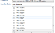
1. Select COM Ports
- Specify UART and DATA COM ports
- Click Connect button.COM StatusMessage should update to show that the COM ports have been connected before continuing.
2. Select Config File
- IMPORTANT: For best performance, calibration should be performed and the mmw_tm_demo_ph2.cfg file should be modified as described in the “Range Bias and Rx Channel Gain/Offset Measurement and Compensation” section of the mmWave SDK documentation for the xwr16xx Out of Box Demo. Save the cfg file to save the calibration parameters.
- This documentation can be found by navigating to
<mmwave_sdk_install_dir>\packages\ti\demo\xwr16xx\mmw\docs\doxygen\html\index.html - The calibration procedure and cfg modification only need to be done once.
- This documentation can be found by navigating to
- By default, the provided cfg file does not enable calibration since this is device specific.
- To load cfg, Click Browse Files and navigate to user’s custom cfg file or the default provided mmw_tm_demo_ph2.cfg in
<mmwave_industrial_toolbox_install_dir>\labs\lab0013-traffic-monitoring-16xx\chirp_configs - Once the cfg has been loaded, the chirp parameter table is populated, if the cfg file included advanced gtrack parameter commands the appropriate tables are also populated.
- THe Scene Preview is updated to reflect the parameters.
OPTIONAL: Advanced Gtrack Parameters
- This section exposes some of the advanced gtrack parameters that are commonly modified for a user’s use case and environment.
- For a detailed explanation of the meaning of the parameters, refer to the TI Design document or the document Tracking radar targets with multiple reflection points located at
<mmwave_industrial_toolbox_install_dir>\labs\lab0013-traffic-monitoring-16xx\src\mss\gtrack\docs - The values of the gtrack parameters can be specified by the command lines in the CFG file or overriden and the values entered in the tables can be used instead. To enable the override, check the checkbox. If the values in the tables are changed without enabling the override, the visualization in Scene Preview will be modified but the gtrack algorithm behavior will not be modified.
3. Scene Geometry
These parameters are to be modified to enable realistic visualization of the scene. They do not affect any processing or algorithm behaviors.
- A) Number of traffic lanes
- B) Lane Width: The number of elements must match the number of traffic lanes. The values represent width in meters and do not have to be identical.
- C) Left lane [m] along x-axis: This specifies the x-axis coordinate of the left most traffic lane. All other lanes are appended towards the right.
- D) Stop bar [m] along y-axis: This specifies the y-axis coordinate of the stop bar.
- E) Start of lane counter: This specifies the y-axis at which to begin counting cars in the scene. Cars between the stop bar and start of lane counter are counted.
Azimuth Angle
- This refers to the azimuth tilt of the radar. This parameter is signed use a + to indicate angled toward the right and – for toward the left. If the EVM is pointed straight down the lanes then the angle would be 0.
- The azimuth angle is specified in the last parameter of the trackingCfg command in the cfg file. However, if there is a discrepency between the value provided in the cfg file and the value specified in the GUI the GUI value will override and take affect.
- If the angle is not specified correctly. Objects will appear to be moving skewed at an incorrect angle relative to actual track.
4. Plotting Area
- F) [Xmin, Xmax]: Refer to the x-axis limits of the plot. Use to zoom in or out of the scene. ( G) [Ymin, Ymax]: Refer to the y-axis limits of the plot. Use to zoom in or out of the scene.
5. Select folder to save data to
Specify the path to save the data that is being visualized. The files each represent 1000 frames of data. Files continue to be created and saved as the visualizer is left running.
3. Launch Visualizer
- Click Start to launch visualizer with configurations specified.
- An example setup figure is included below:

4. Understanding the Output

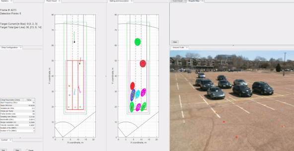
The visualizer consists of:
- 1st plot panel (left) with a Point Cloud plot.
- The black points represent the point cloud returned by the detection layer of the device.
- Each new tracked object is assigned one of five possible colors (blue, red, green, cyan, and magenta).
- The small colored ring represents the computed centroid of the point cloud for the tracked object.
- The “snail trail” trace represent 100 frames of history of the tracked object’s centroid.
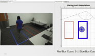
- 2nd plot panel (right) with a Gating and Association plot.
- This plot visualizes the result of the tracking algorithm.
- The bubble is centered over the centroid of of the tracked object.
- A side panel with Statistics and Visualizer Options
- The video stream of the vehicles are superimposed for illustrative purposes and is not a provided feature.
Quitting the Visualizer : To exit the visualizer use the exit button at the bottom left of the window. This will delete the open serial ports and finish saving.
Developer’s Guide
Build the Firmware from Source Code
1. Software Requirements
| Tool | Version | Required For | Details |
|---|---|---|---|
| mmWave Industrial Toolbox | Latest | – | Contains all files (quickstart, visualizer and firmware source files) related to the lab |
| TI mmWave SDK | 2.00.00.04 | Firmware Source Code | SDK Version 2.00.00.04 MUST be used. Any other version will not work. The specific version can be downloaded here: TI mmWave SDK 2.00.00.04 |
| Code Composer Studio | 7.2+ | Firmware Source Code | Download link Note: CCSv6.x cannot be used |
| C6000 Code Generation Tool | 7.4.16 | Firmware Source Code | To compile code for the DSP core(C674x), the version 7.4.16 compiler must be installed under C:\ti. Download link |
The Traffic Monitoring Demo requires mmWave SDK version 2.00.00.04. Other versions will currently not work. Ensure that the specific verision has been installed.
To verify proper installations, navigate to C:\ti and ensure that the following tools have been installed in the EXACT directory specified.
| Tool | Version | Folder Path | Download link & Details |
|---|---|---|---|
| CCS | 7.2 or later | C:\ti\ccsv7 | Download link Note: CCSv6.x cannot be used |
| TI SYS/BIOS | 6.52.00.12 | C:\ti\bios_6_52_00_12 | Included in mmwave sdk installer |
| TI ARM compiler | 16.9.1.LTS | C:\ti\ti-cgt-arm_16.9.1.LTS | Included in mmwave sdk installer |
| TI CGT compiler | 7.4.16 | C:\ti\c6000_7.4.16 | Version 7.4.16 must be downloaded and installed. Download link |
| XDC | 3.50.00.10 | C:\ti\xdctools_3_50_00_10_core | Included in mmwave sdk installer |
| C64x+ DSPLIB | 3.4.0.0 | C:\ti\dsplib_c64Px_3_4_0_0 | Included in mmwave sdk installer |
| C674x DSPLIB | 3.4.0.0 | C:\ti\dsplib_c674x_3_4_0_0 | Included in mmwave sdk installer |
| C674x MATHLIB | 3.1.2.1 | C:\ti\mathlib_c674x_3_1_2_1 | Included in mmwave sdk installer |
| mmWave device support packages | 1.5.3 or later | – | Upgrade to the latest using CCS update process (see SDK user guide for more details) |
| TI Emulators package | 6.0.0576.0 or later | – | Upgrade to the latest using CCS update process (see SDK user guide for more details) |
2. Import Lab Project
For the Traffic Monitoring lab, there are two projects, the DSS for the C674x DSP core and the MSS project for the R4F core, that need to be imported to CCS and compiled to generate firmware for the xWR1642.
- Start CCS and setup workspace as desired.
- Import the projects below to CCS using either TI Resource Explorer in CCS or CCS Import Projectspecs method:
- traffic_monitoring_16xx_dss
- traffic_monitoring_16xx_mss
Expand for details on importing via TI Resource Explorer in CCS
Expand for details on importing via CCS Import Projectspecs
Successful Import to IDE
After using either method, both project should be visible in CCS Project Explorer
Project Workspace
When importing projects to a workspace, a copy is created in the workspace. All modifications will only be implemented for the workspace copy. The original project downloaded in mmWave Industrial Toolbox is not touched.
3. Build the Lab
Build DSS Project
The DSS project must be built before the MSS project.
The DSS project must be built using compiler version 7.4.16. To check the build settings, select traffic_monitoring_16xx_dss and right click on the project to select Show build settings…. Under the General tab, the Advanced Settings section has a drop down menu for Compiler Version. Ensure that it reads TI v7.4.16.
With the traffic_monitoring_16xx_dss project selected in Project Explorer, right click on the project and select Rebuild Project. Selecting Rebuild instead of Build ensures that the project is always re-compiled. This is especially important in case the previous build failed with errors.
Successful DSS Project Build
In the Project Explorer panel, navigate to and expand traffic_monitoring_16xx_dss > Debugdirectory. The project has been successfully built if the following files appear in the Debugfolder:
- xwr16xx_traffic_monitoring_dss.bin
- xwr16xx_traffic_monitoring_dss.xe674
Build MSS Project
After the DSS project is successfully built, select traffic_monitoring_16xx_mss in Project Explorer, right click on the project and select Rebuild Project.
Successful MSS Project Build
In the Project Explorer panel, navigate to and expand traffic_monitoring_16xx_mss > Debugdirectory. The project has been successfully built if the following files appear in the Debugfolder:
- xwr16xx_traffic_monitoring_mss.bin
- xwr16xx_traffic_monitoring_mss.xer4f
- xwr16xx_traffic_monitoring_lab.bin
Build Fails with Errors
If the build fails with errors, please ensure that all the prerequisites are installed as mentioned in the mmWave SDK release notes.
4. Execute the Lab
There are two ways to execute the compiled code on the EVM:
- Deployment mode: the EVM boots autonomously from flash and starts running the bin image
- Using Uniflash, flash the xwr16xx_traffic_monitoring_lab.bin found at
<PROJECT_WORKSPACE_DIR>\traffic_monitoring_16xx_mss\Debug\xwr16xx_traffic_monitoring_lab.bin - The same procedure for flashing can be use as detailed in the Quickstart Flash the Devicesection.
- Using Uniflash, flash the xwr16xx_traffic_monitoring_lab.bin found at
- Debug mode: enables connection with CCS while lab is running; useful during development and debugging
Expand for help with Debug mode:
After executing the lab using either method, the lab can be visualized using the Quick Start GUI or continue to working with the GUI Source Code
转载请注明:悠瞅の博客 » Ti xWR1642 Traffic Monitoring